3d printed quadcopter


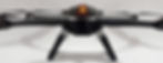
This is my first major project i made with my 3d printer .My goal was , be able to create a quadcopter easy to carry and different than a foldable one. I decided to create a splitable one.
this way i have a 28 inch quad and i can put away in a 14 inch x14 inch x 6 inch carry case.
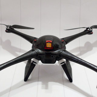
The biggest challenge here was the connector ,how i was connect the power , how i can print to get my printed part strong enough and wich plastic i will use to get those property. First i decided to put my esc in the main body part this way is more easy to just pass the current for those brushless motor instead passing power plus esc connection this mean more potentiel problem . second i choose to use nylon 910 from taulman ,this nylon is amaizing strong , the layer bonding is exellent . now the next step is how i will print that , i had to do a couple of fail before understanding the way i should split this part to get the best of it .


the next part im currently working now is the camera gimbal .I choose to use a simple 2 axis because i don't have retractable landing gear. So there the next challenge will be following the quad copter design. The Quad still need to be easy to cary and fit in a 14 x 14 x 6 inch case so that mean i need to follow the plug an unplug thing int the gimbal also . I will need to design a clip that will lock the system at the bottom of the quadcopter. After a couple of days thinking that is a first design i come with.

Alot of my trouble was about the clip . i was thinking of using a spring system or an elatic system to make it work but after thinking i come with this idea , why not just using the natural spring of the nylon material. This way i save a lot in complexity and potentiel jam. so here is a side view of the base plate .

The clip is the white part like a bird head down in the top lef of the design . To have this part working well an benefit the max strenght when i will print it , i need to print it side on the print bed. This way the paslic flow will be align an will be perpendicular to the apply force .

now my clip solved i need to i need to integrate all my electronic in the gimbal removable base this was i just need to feed the power connector thats mean two connection instead of six , 3 connectors by motor.


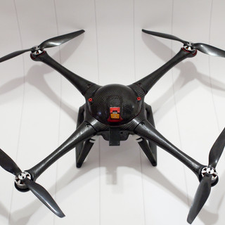
still waiting to get my gimbal controller to finish my design , will start to reprint my longer legs ,with those i will have enough space for my camera gimbal so here is the news design
because they are bigger than my printer can print i had no choice to break the part in two half . because now i have two part, instead of using glue to fix the two part i will use two 3mm bolt its more though and if for any reason one side break i can easely reprint this section.

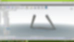
below im showing in simplify3d how i gone a print thise file .i have choose to print this layed on the side

this way i can get the print layer be 90 degre of the mechanical tenssion as the red arrow are showing for sure is not the best way to get sexy finish for this part bot the best to get the best mechanical property.
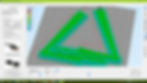
for this im using 3 outside layers and 18 % filling honeycomb fill this may take 12 hours to print at 100 micros maybe .